
SCSI Toolbox :: Newsletter - August 2008
IN THIS EDITION
- SAT Article
- Hands-on training with a technical STB expert!
- Ask Dr. SCSI - "When I do a BAM trace, I see a lot of SRB phase types. How do I interpret the information displayed in the SRB phase?"
- Issuing ATA/SATA Commands Article
- SCSItoolbox Suite version 7.2 Available for immediate download
- SCSItoolbox Suite Corporate Licensing available
This SAT article features information on SAT. The article will explain what SAT is, if you need it, and if your controller supports among other things.
SAT (SCSI->ATA Translation) is a mechanism whereby ATA task register commands may be sent to a device which is seen by the operating system as a SCSI device. This is most often the case when SATA drives are connected to an add-in PCI bus type of SATA controller card. Even though the card is a SATA controller in most cases Windows will see the controller as if it were a SCSI HBA, and so will not allow you to issue ATA task register level commands to the connected devices.
Contents of Article
What is SAT?
How do I know that I need to use SAT?
Does my controller card support SAT?
A Simple test command
Issuing the ATA SMART command
Details of defining an IDENTIFY command
Details of defining a SMART command
Conclusion
Download the article here - UsingSAT.pdf
![]()
Hands-on training with a technical STB expert!
![]()
Do you have questions about how to best use the STB Suite in your business? STB is happy to work with you in an interactive “live” environment to help you get the most out of your Toolbox. The cost? If you are a current Performa customer it is free! The commitment? Training sessions run between 30 and 60 minutes.
Here is a list of some recent customer training sessions that STB has conducted - live, interactive web sessions presented by STB programmers:
- Three stages of disk drive screening
- How to troubleshoot tape drive problems
- RAID issues in disk drive testing
Contact Jeremy Wolfe at (720) 249-2641 today to schedule your own custom training session!
![]()
Ask Dr. SCSI - "When I do a BAM trace, I see a lot of SRB phase types. How do I interpret the information displayed in the SRB phase?"
 Q. “When I do a BAM trace, I see a lot of SRB phase types. How do I interpret the information displayed in the SRB phase?”
A. “The first 16 bytes of the SRB have the following information:
Bytes 0-thru-1: Length
Byte 2: Function
Byte 3 bits 0-thru-5: SRB Status
Byte 3 bit 6: Queue-frozen bit
Byte 3 bit 7: Auto-sense valid bit
Byte 4: Scsi Status
Byte 5-thru-7: PathID,TargetID,Lun
Byte 8-thru-9: QueueTag,QueueAction
Byte 10: CDB Length
Byte 11: Sense Info Buffer Length
Byte 12: SRB Flags
Let’s take a look at the following SRB phase:
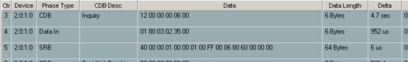
The Length field is hex ’40 00’ or decimal 64.
The Function field is ‘00’: some of the most common values for this field are
0 = SRB_FUNCTION_EXECUTE_SCSI
4 = SRB_FUNCTION_RELEASE_QUEUE
The SRB Status field is ‘01’: some of the most common values for this field are
1 = SRB_STATUS_SUCCESS
2 = SRB_STATUS_ABORTED
4 = SRB_STATUS_ERROR
‘0A’ = SRB_STATUS_SELECTION_TIMEOUT
‘12’ = SRB_STATUS_DATA_OVERRUN
The Scsi Status field at byte 4 is ‘00’ – this indicates there was no check condition. If the field is ‘02’ then the target issued a check condition (so there would be sense data available to evaluate)
The PathID,TargetID,Lun fields at bytes 5,6,7 are ’00 01 00’ – this means PathID = 0, TargetID = 1, Lun = 0. Notice these are indicated under the “Device” column
The CDB Length field at byte 10 is ‘06’. Notice the command that was issued was an Inquiry command and this command is 6-bytes long.
The Sense Info Buffer Length field at byte 11 is ‘80’ or decimal 128
Now let’s take a look at an SRB associated with a command where the target rejects the command. In the below output, the Device 5:0:0:0 is a disk drive and we are attempting to send it a library command “Read Element Status”. It rejects the command with a check condition and sends the sense data.
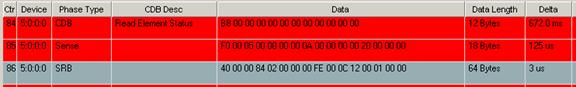
Look at byte 3 – it is hex ‘84’. Bits 0-thru-5 are hex ‘04’, bit 6 is 0, bit 7 is 1. The interpretation of this is the SRB Status is 4 (srb status error), and the AutoSense Valid bit is 1.
Notice that the Scsi Status field is ‘02’ – this indicates the target issued a check condition.
The CDB Length is ‘0C’ or decimal 12 and the Read Element Status command is 12-bytes long.
The Sense Info Buffer Length is ‘12’ or decimal 18 – the driver in this case only provided an 18-byte buffer for sense data. Note that many devices may return much more sense data than 18 bytes!!
The following example is quite interesting – a “Mode Sense” command was issued with a buffer that has 255-bytes available but the target only has 12 bytes to return. Here we see two SRBs associated with this command (in the “Ctr” column these SRBs are Ctr=45 and Ctr=45)
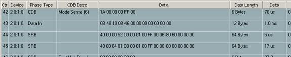
In the SRB on Ctr = 44, at byte 3 we see ‘52’ so bits 0-thru-5 is ‘12’ which is an SRB Status of SRB_STATUS_DATA_OVERRUN. Notice also that the Scsi Status at byte 4 is 0 (i.e. no error) so this is a completely normal event.
In the SRB on Ctr = 45, we see some oddities: Normally the Function field at byte 2 is ‘00’ but this time it is ‘04’ or SRB_FUNCTION_RELEASE_QUEUE. Almost always a data overrun SRB has a corresponding release queue SRB.
In our final example, a “Test Unit Ready” command is issued and we have two SRBs associated with the command.
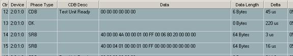
At Ctr = 14 we have the first of the two SRBs – the SRB Status (at byte 3 bit 0-thru-5) is ‘0A’ or Selection Timeout. The Queue Frozen bit is also ‘1’. Notice that in the following SRB (Ctr = 15) we see a “release queue” SRB.
![]()
Issuing ATA/SATA Commands Article
 Here's another exclusive article from STB including what is involved with issuing ATA/SATA Commands.
ATA commands, also referred to as ATA task register commands, are commands issued to ATA or SATA interface storage devices. From now on in this article when we refer to ATA we mean this to include both ATA and SATA devices.
ATA commands are used to write and read data from ATA drives, as well as to set various device parameters and to read device health data.
Task registers refers to the original hardware interface to these devices which consisted of seven separate registers. These seven registers were loaded with the appropriate values and were then transferred to the drive, where the drive would interpret from the registers what it was being asked to do, and would then (hopefully) complete the command.
Download and and read the full article here - IssuingATACommands.pdf
![]()
SCSItoolbox Suite version 7.2 Available for immediate download ![]()
The SCSItoolbox Suite version 7.2 is available for immediate download for Active Performa customers. If you have not received your download information already you can contact Jeremy Wolfe to receive your 7.2 upgrade. The feature list as well as the Release notes are available online and here. Release Notes 7.2 | 7.2 Feature List
If you would like to purchase the Performa upgrade for your STB License you can purchase online here: http://scsitoolbox.com/products/performa/default.asp?product=STB or you can call Jeremy Wolfe at 720.249.2641 or via email sales@scsitoolbox.com.
![]() Corporate
Licensing for SCSItoolbox Suite Products
Corporate
Licensing for SCSItoolbox Suite Products
![]() Could your company use more than a combined 20 licenses of the SCSItoolbox
and/or Developer Toolbox? Are you tired of using the hardware keys that
are required for the Toolbox Products? You might want to take a closer
look at our Corporate licensing options that include features like:
Could your company use more than a combined 20 licenses of the SCSItoolbox
and/or Developer Toolbox? Are you tired of using the hardware keys that
are required for the Toolbox Products? You might want to take a closer
look at our Corporate licensing options that include features like:
- Unlimited Corporate usage of SCSItoolbox Suite Products
- Special OEM build of STB products eliminates hardware keys
- Surprisingly affordable pricing structure
- Onsite Training
Contact Sales to find out if a Corporate Site License for SCSI Toolbox Products is right for you.